対象バージョン:Blender v2.82a
Texture Mappingは偉大
3DCGを作成するにも、3Dゲームを作るにしても、3Dモデルが単色では少し味気ないですね。
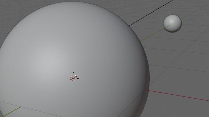
上の画像に、NASAが無料で公開している画像データ(NASA Visible earth、CGI Moon Kit)をテクスチャとして貼り付けると以下の様になります。
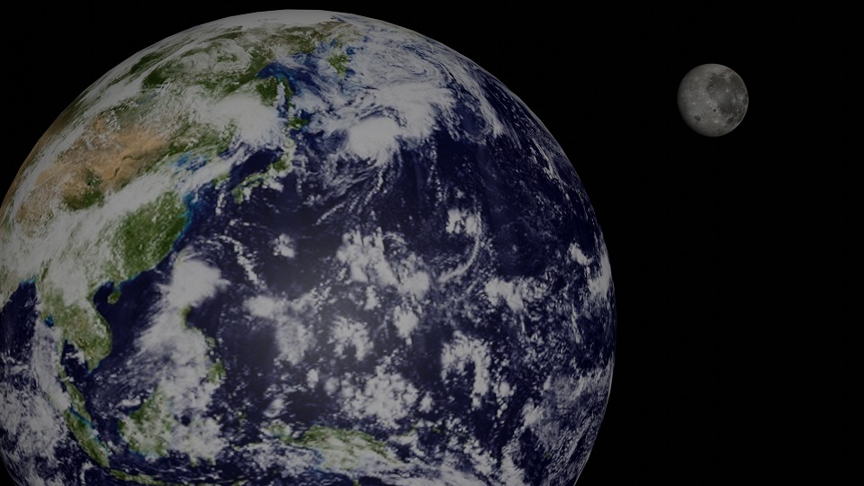
2つのUV Sphereにテクスチャを貼るだけで、ぐっとクオリティが上がりますね。
今回はオブジェクトにTexture Mappingについて見ていきます。
サイコロの作成
最も単純なTexture Mappingの例として、Cubeを使ってサイコロを作成してみます。
Cubeの配置
何はともあれ、Cubeを1つ画面に配置します。
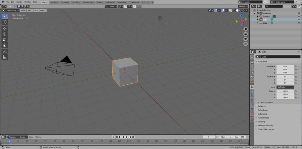
※以降の手順については、色々なやり方があるとは思います。自分のやりやすい手順を試してみてください。
Image Textureの設定
さて、CubeのTexture Mapping用の画像を用意しなければなりません。
Materialの追加
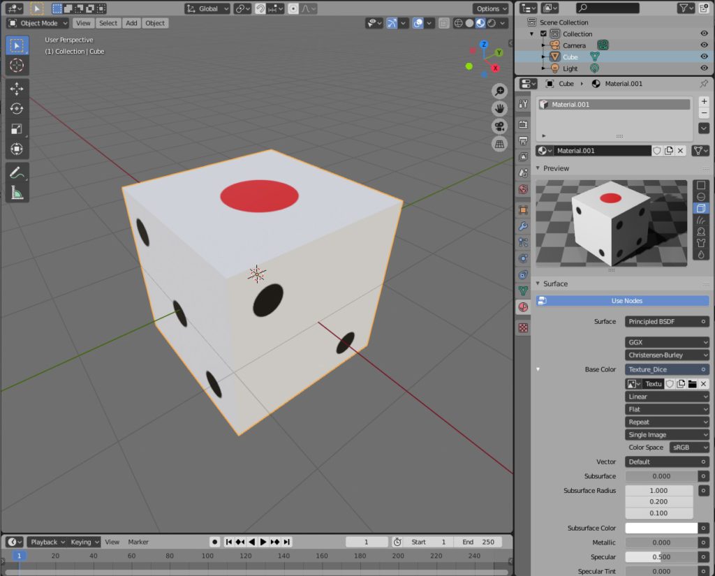
Cubeを選択し、PropertiesパネルのMaterial Propertiesタブを選択し、[New]ボタンを押し、CubeにMaterialを追加します。
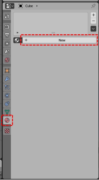
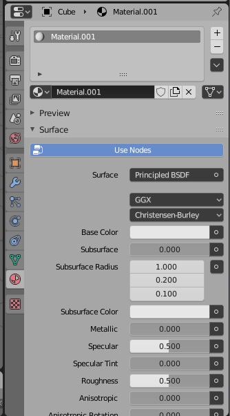
Image Textureの設定
[Base Color]の右側の[○]を押し、表示される選択肢の中から[Image Texture]を選択します。
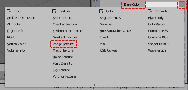
Image Textureの下部の[New]ボタンを押します。
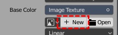
表示されたダイアログで[Name]を”Texture_Dice”とし、[Color]を白にして、[OK]ボタンを押します。(サイコロの大部分は白なので)
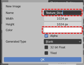
画像サイズはBlenderでは特に制限はないようですが、他のソフトやアプリでは、一辺の長さが2のべき乗の正方形の方を前提としているものもあるので、このままにしておきます。
この時点では、特に何も変わりませんが、Material Propertiesタブの[Preview]を開いて、右側の形状を立方体を選択してみます。
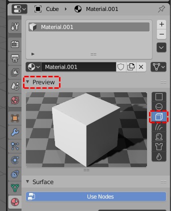
今の状態では、白い箱が表示されているだけですね。
Texture Paintワークスペース
ワークスペースの切替
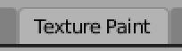
サイコロの目を作成するために、トップバーの[Texture Paint]を押して、UV Editingワークスペースを開きます。
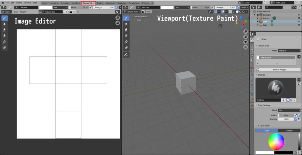
左側がImage Editor、右側がTexture Paintモードになりました。
右側のViewportのShadingモードをMaterial Previewにしておきます。(描画が反映される様に)
展開図の対応確認
Image EditorではCube(立方体)の展開図がガイドとして表示されていますが、Cubeのどの面がどこに対応しているかが分かりません。
Viewport側のペンの色を赤くし、BrushのRadius(半径)を10程度にし、Cubeの上の面にサイコロの1の目を示す印をつけます。
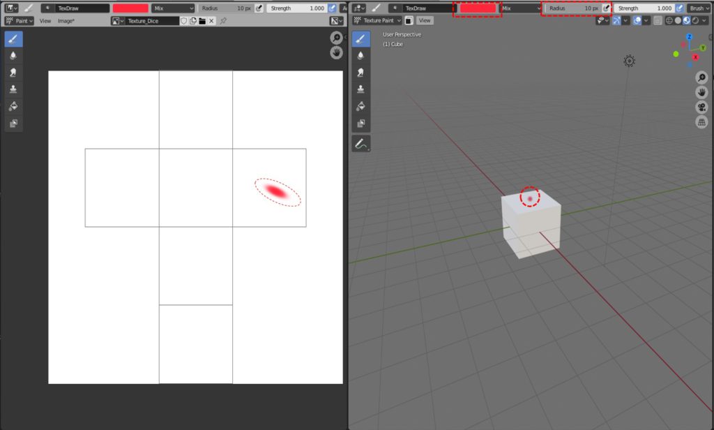
Viewport側にペイントすると、Image Editor側にもペイント結果が反映されます。(Viewportの斜めの面にペイントすると、Image Editor側は歪ますが…)
これで、サイコロ1の面が分かりましたので、続きはImage Editor側で行います。
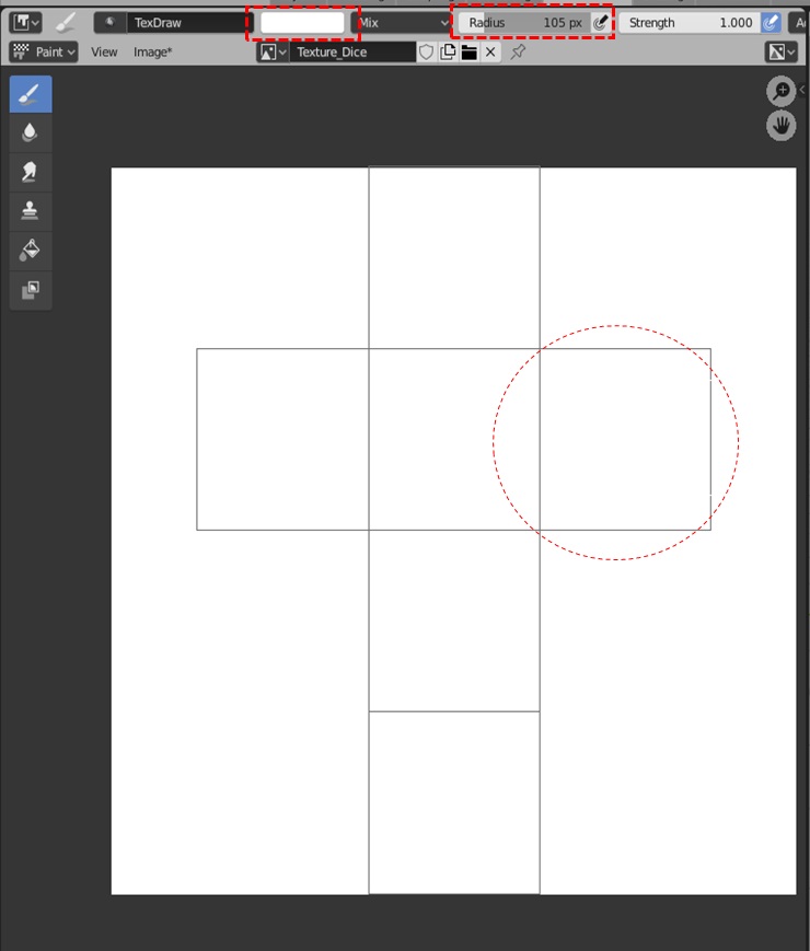
最初に先ほど付けた印を消します(白で上塗りします)。
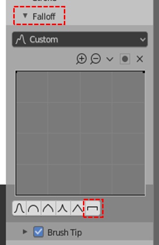
サイコロの目を描くために、ブラシの形状を変更します。(今のままでは、周辺がぼやけているので、サイコロの目もぼやけたものになってしまうので)
サイドバーを開き、ToolタブのFalloff項目を開き、Preset Brush Shapeで一番右側のぼかしなしの形状を選択します。
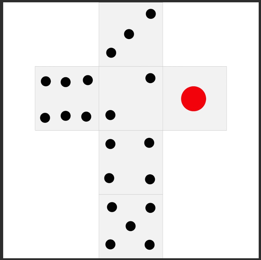
後は、ブラシのサイズと色を調整して、サイコロの目を描きこんで行きます。
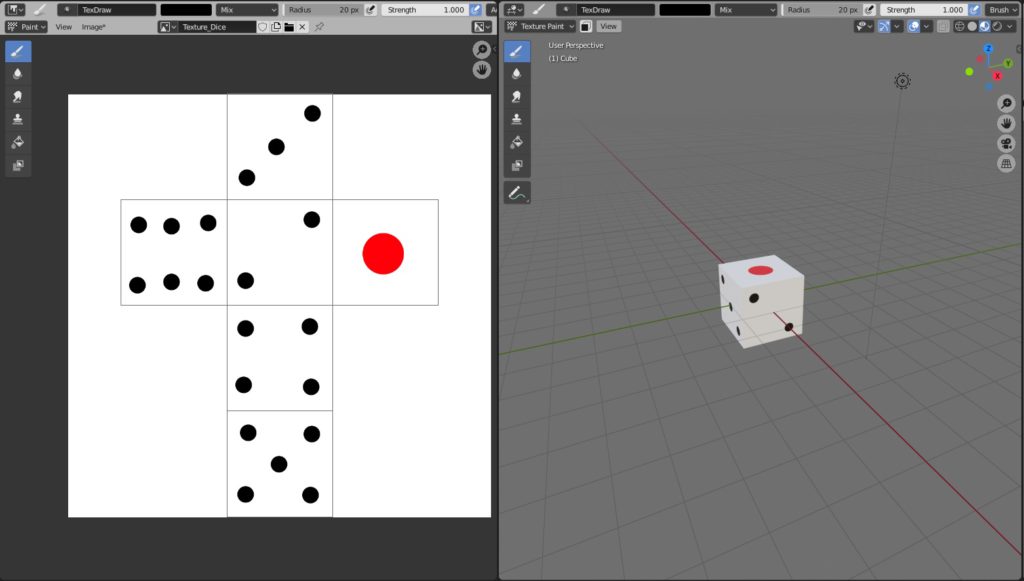
Image Editorに目を描きこんで行けば、右側のViewport側にも反映されてサイコロになっていきます。
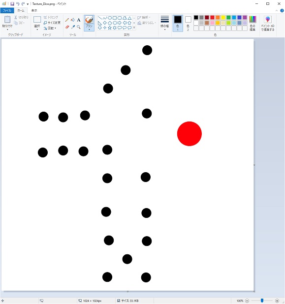
BlenderのImage Editorでも簡単な描画は可能ですが、やはり使い慣れたツールで描画したいと思う事もあるかと思います。
その場合は、[Image]メニューの[Save]もしくは[Save as]でファイルへ保存し、その後、[Image]メニューの[Edit Externally]を選択すれば、外部エディタが開きます。
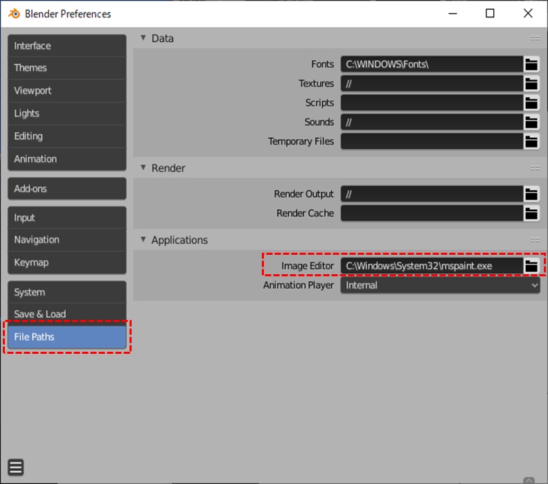
外部エディタを起動するには、Preferencesに予め設定しておく必要があります。
外部エディタを起動できても、展開図の線がないと境界が分かりにくいですね。
それは別の方法で出力します。(が、MSペイントでは活かしきれないですが…)
UV Editingワークスペース
トップバーの[UV Editing]を押して、UV Editingワークスペースを開きます。
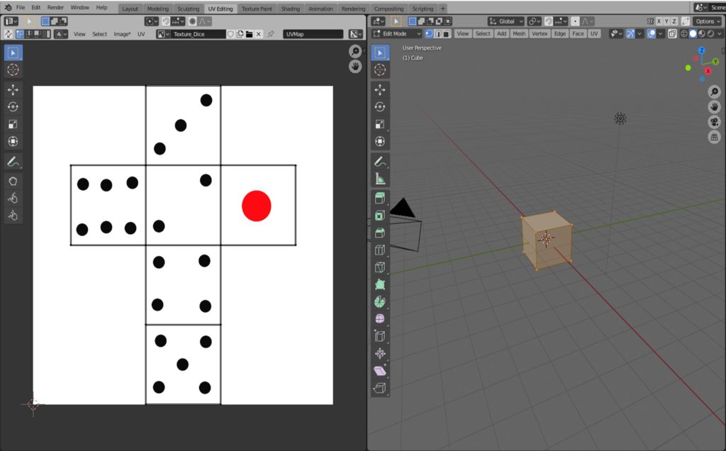
ぱっと見、[Texture Paint]ワークスペースになっていますが、左側はUV Editorとなっています。
UV Editorでは、画像の編集ではなく、オブジェクト(Cube)の展開図(UV Map)の配置を編集できるものです。
ViewportのVertexやEdgeを編集するようにUV EditorのUV MapのVertex/Edgeを編集できます。BlenderのUV展開図を修正したい場合に使いますが、ここでは特に何もしません。
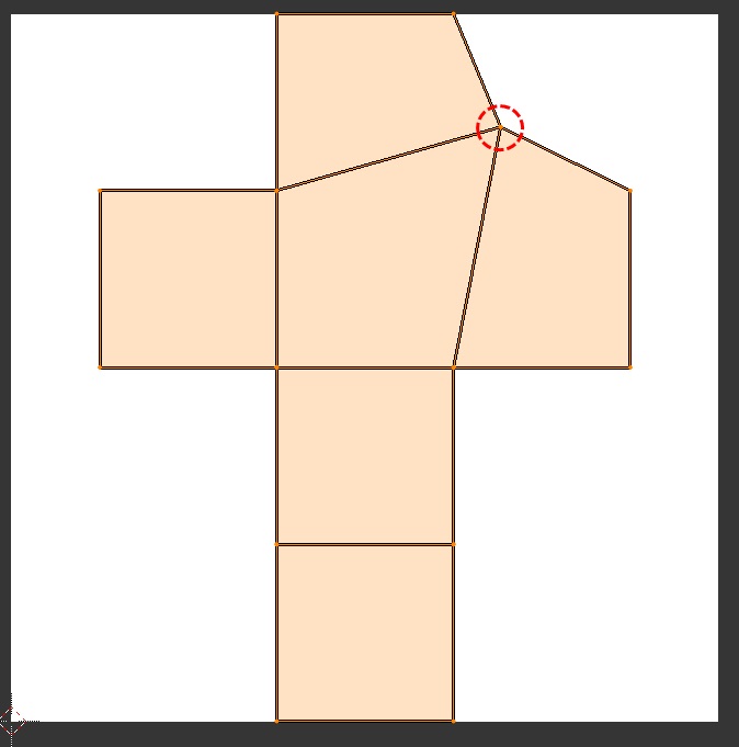
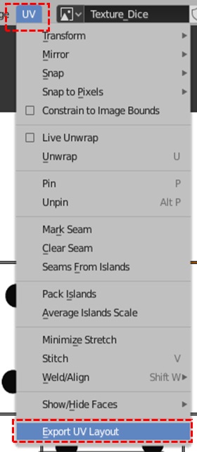
今回は、[UV]メニューから[Export UV Layout]を選択して、展開図の枠線データを画像として出力します。(名前は”Layout_Dice.png”などの様にします)
ちょっとわかりにくいですが、周辺は透過、面部分は半透過のデータとなっています。

レイヤー機能を持ったペイントツールなどを利用すれば、先ほど出力したテクスチャ画像と重ね合わせながら描画が可能になります。
外部ツールで編集したデータを再度、Blenderで読み込めば、修正が反映されます。
サイコロの完成
以上でサイコロは完成です。
Cube(立方体)のTexture Mappingは非常にシンプルでした。
次回以降はもう少し複雑な形状のオブジェクトのTexture Mappingを見ていきます。
コメント